

A hydraulic press uses a hydraulic system to generate the force required for operations such as metal forming, stamping, deep drawing, powder compaction, press-fitting, and material compression. Hydraulic fluid transmits pressure through the system, allowing a hydraulic cylinder to move the slide and apply force to the workpiece held in the die.
A complete hydraulic system consists of more than just a pump and a cylinder. It includes four main groups of components: power components, actuators, control elements, and auxiliary components. These components work together to determine the press's output force, operating speed, movement control, and overall stability.
Hydraulic pump
A hydraulic pump is the primary power component in a hydraulic system. Its main function is to draw hydraulic fluid from a reservoir and deliver it into the hydraulic circuitry, thereby providing the necessary flow for the system.
When driven by an electric motor, the hydraulic pump forces fluid into the system. As the fluid encounters resistance from a load, pressure is generated; the pressurized fluid then flows through control valves into a hydraulic cylinder, driving the movement of a piston. In our hydraulic presses, we typically use plunger pumps (piston pumps), which are well-suited for high-pressure applications or systems that require more flexible flow control.
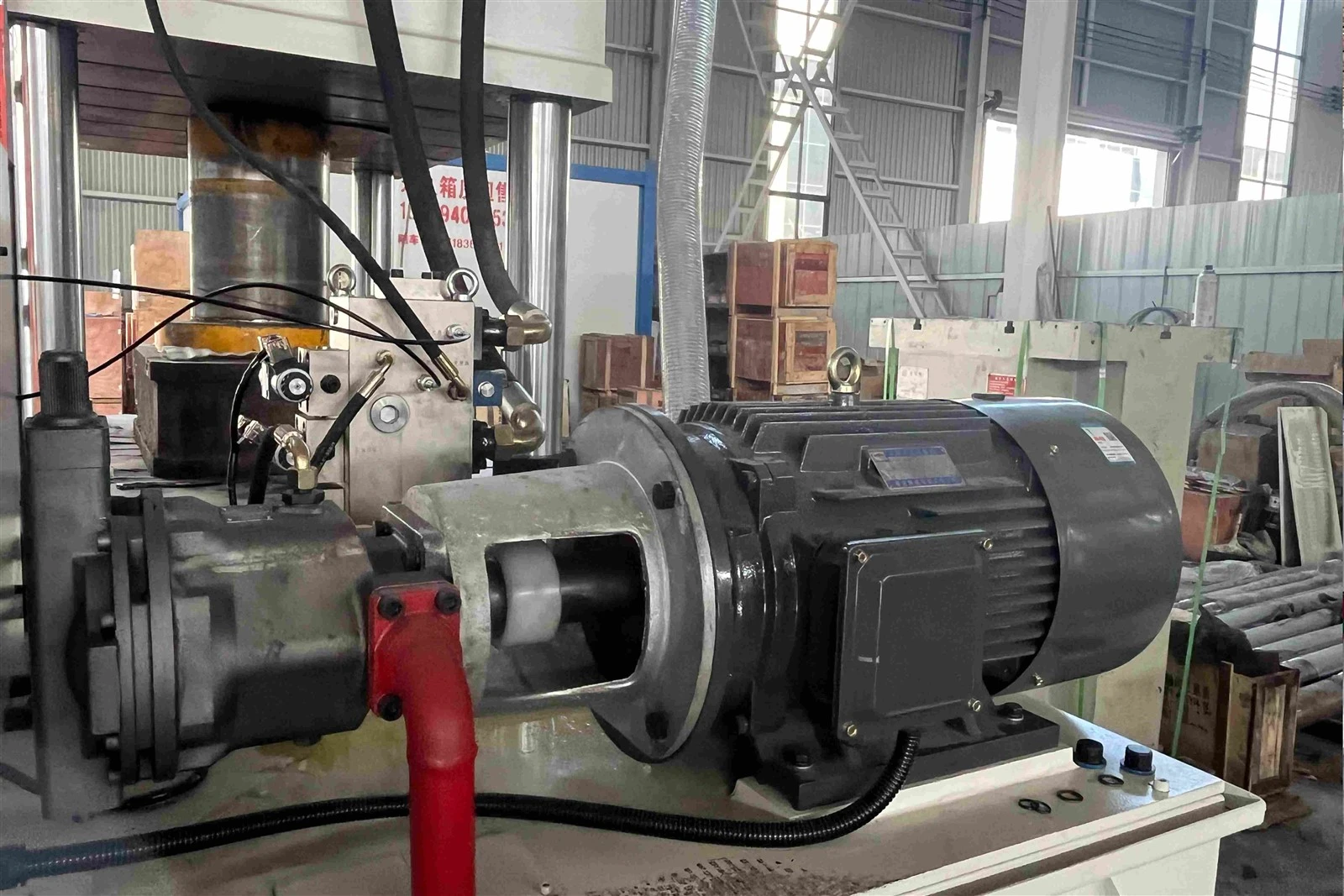
It is important to note that a hydraulic pump is primarily responsible for supplying flow. The actual operating pressure of a hydraulic system is determined by the load and the system's control conditions-it is not decided by the hydraulic pump alone.
Hydraulic Cylinder
A hydraulic cylinder converts hydraulic pressure into linear motion, driving the slide or movable worktable to perform pressing operations.
When high-pressure hydraulic fluid enters the cylinder, it pushes against the piston, causing the piston rod to extend or retract. The thrust generated by the hydraulic cylinder depends on the operating pressure and the piston's effective working area.
During operation, the hydraulic cylinder moves through a series of stages according to the specific manufacturing process. These typically include rapid descent, pressurization, pressure holding, and return.
The dimensions and configuration of the hydraulic cylinder vary depending on the rated pressing capacity and working stroke of the hydraulic press.
Hydraulic valves control the flow and pressure of hydraulic fluid within a hydraulic system. Their selection and configuration must be matched to the hydraulic pump, cylinders, and operating requirements of the equipment.
Based on their functions, hydraulic valves are generally divided into the following three categories:
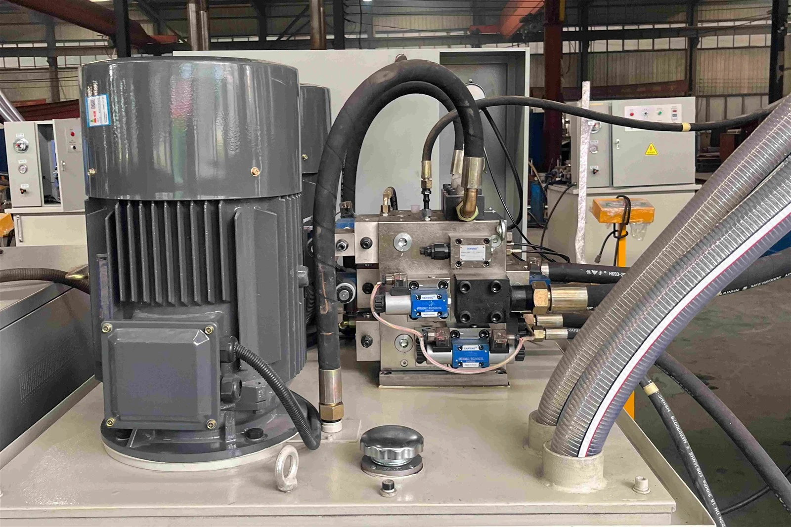
Directional Control Valves
Directional control valves are primarily responsible for altering the flow direction of the hydraulic fluid, enabling hydraulic cylinders to perform actions such as extending (downward stroke), stopping, and retracting (return stroke).
Pressure Control Valves
Pressure control valves are used to regulate or limit the pressure within a hydraulic system. For instance, a relief valve can cap the system's maximum pressure, preventing it from exceeding a set limit and thereby protecting the hydraulic pump, piping, and other components from damage.
Flow Control Valves
Flow control valves are primarily used to regulate the flow rate of the hydraulic fluid, which in turn dictates the operating speed of the hydraulic cylinders. Depending on the specific process requirements, these valves allow for the precise control of speeds during rapid downward movement, pressurized operation, and the return stroke.
Hydraulic Reservoir
A hydraulic reservoir is used to store hydraulic fluid in a hydraulic system. In addition to supplying fluid to the hydraulic pump, it helps dissipate heat, allows entrained air to escape, and provides space for solid contaminants to settle at the bottom of the tank.
The hydraulic pump draws fluid from the reservoir and delivers it through the hydraulic lines and control components. After passing through the system, the fluid returns to the reservoir through the return line, completing the circulation cycle.
A hydraulic reservoir is typically equipped with the following components:
Fluid Level Gauge: Allows operators to check the hydraulic fluid level inside the reservoir.
Air Breather (Air Filter): Helps prevent dust and other airborne contaminants from entering the reservoir while allowing air to move in and out as the fluid level changes.
Drain Port: Provides an outlet for draining used hydraulic fluid during maintenance and replacement.
Temperature Monitoring Device: Monitors the temperature of the hydraulic fluid during operation.
The reservoir capacity should be selected according to the hydraulic system's flow rate, equipment operating frequency, and heat dissipation requirements.
Hydraulic Lines, Hoses, and Fittings
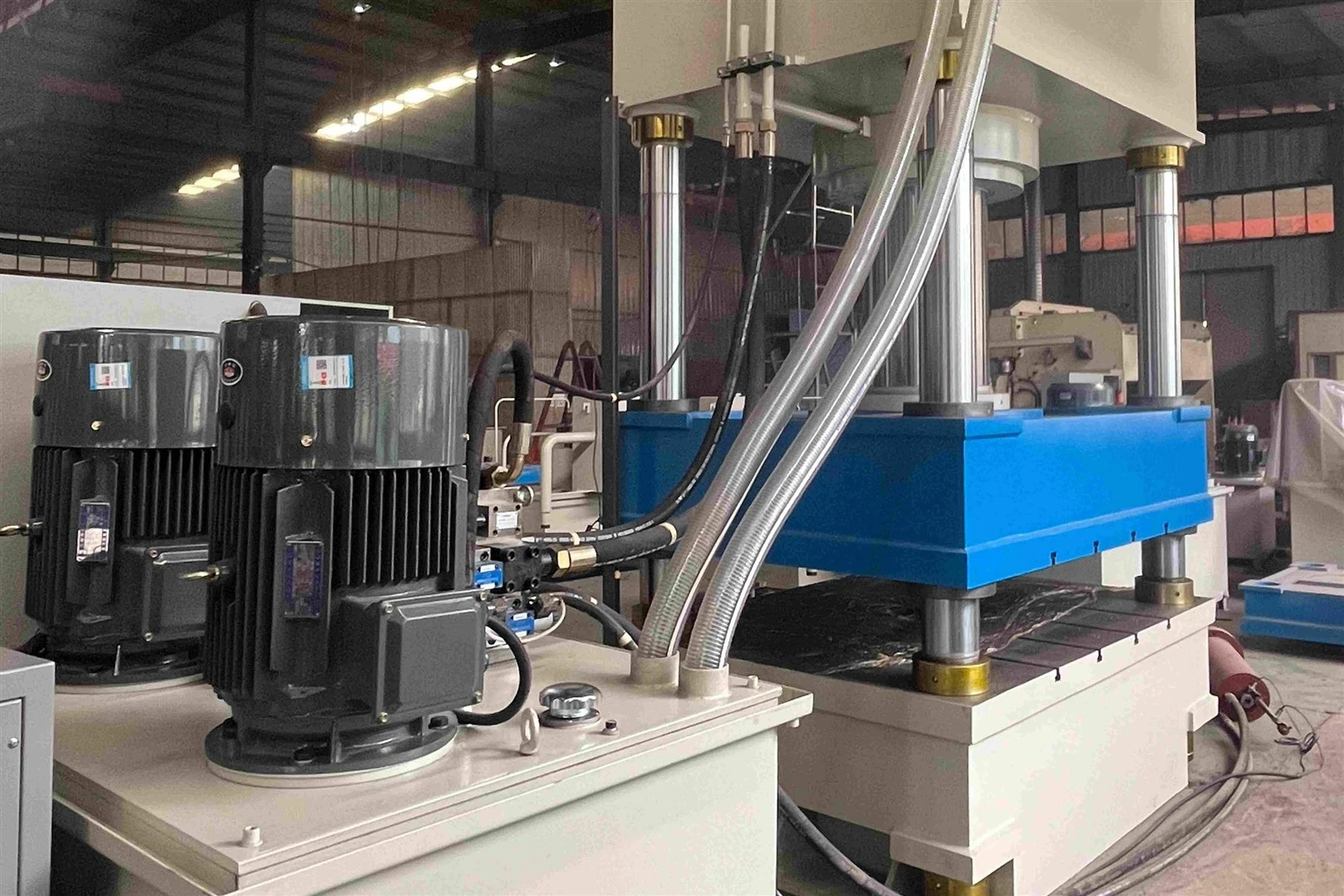
Hydraulic lines connect the hydraulic pump, valves, cylinders, and reservoir, allowing hydraulic fluid to flow through the system along a defined path. Depending on the installation location and equipment configuration, a hydraulic system may use rigid steel tubing or high-pressure hydraulic hoses.
When selecting hydraulic lines, several factors need to be considered, including operating pressure, fluid flow rate, pipe or hose diameter, available installation space, and vibration during equipment operation.
Incorrect pipe or hose sizing, poor sealing at fittings, or low-quality hoses can lead to problems such as fluid leakage and pressure loss, potentially affecting the proper operation of the equipment.
During prolonged operation, hydraulic fluid in a hydraulic press generates heat due to internal friction, throttling, and pressure losses. If the oil temperature continues to rise, it can affect the fluid's viscosity, sealing performance, and the service life of hydraulic components.
Depending on the machine's power rating, operating frequency, and working environment, the hydraulic press can be equipped with either an air-cooled or a water-cooled system.
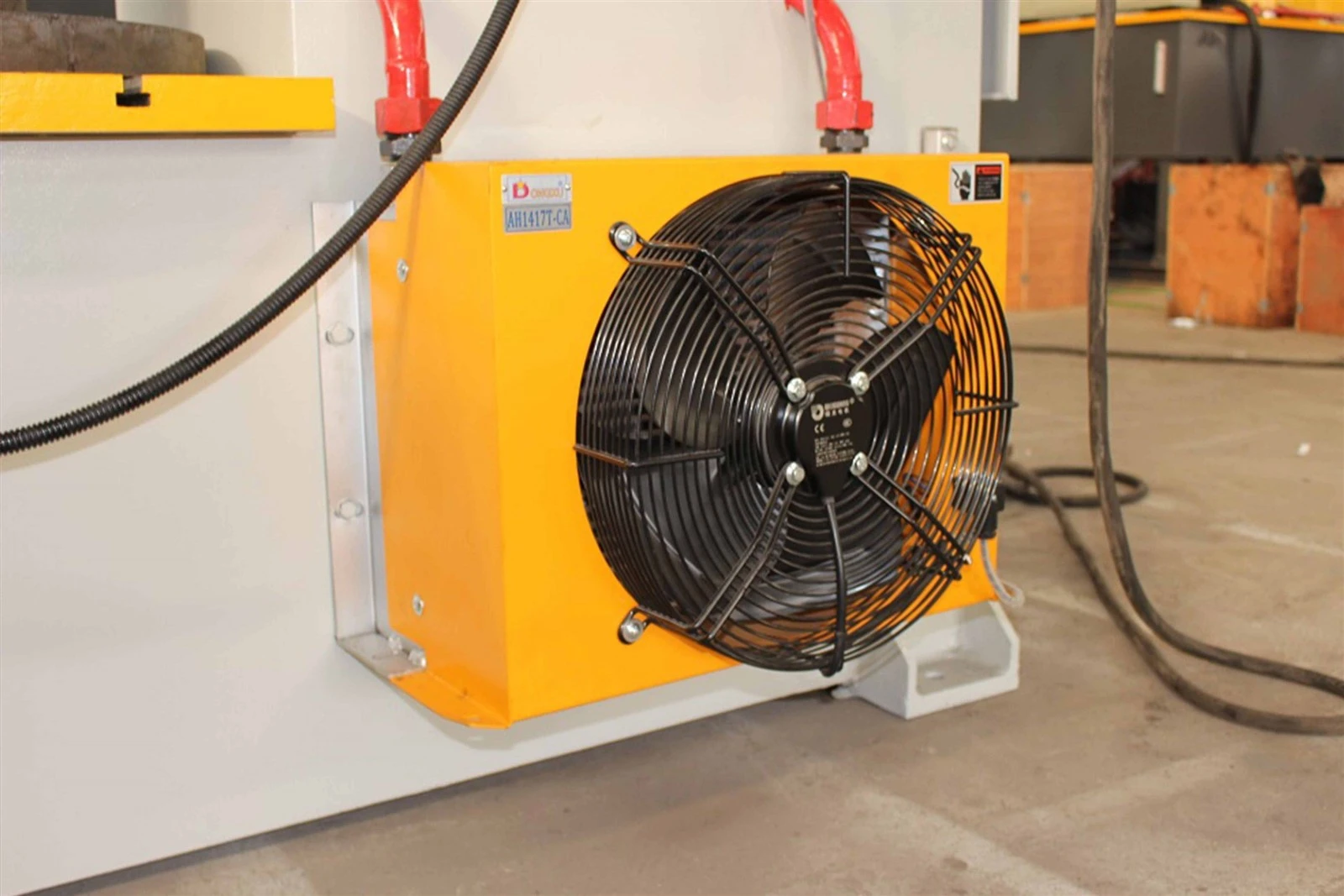
Air cooling
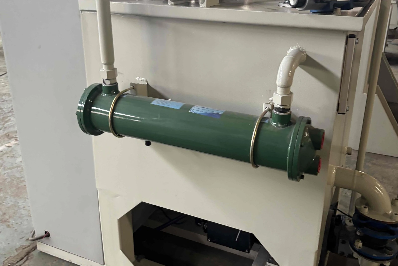
Water cooling
Electrical Control System
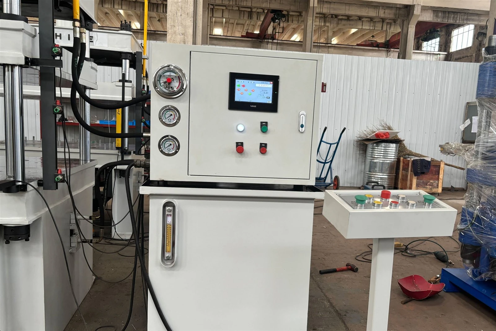
The electrical control system works together with the hydraulic system to control the electric motor, hydraulic valves, and related actuators. It ensures that the machine carries out each stage of its operating cycle according to a preset program.
The electrical control system can be configured according to the products being manufactured, their dimensions, and the required production process. Control options range from conventional electrical controls to PLC-based systems and other automation configurations.
Taking a typical hydraulic forming process as an example, the machine generally follows this sequence:
Rapid Descent: The slide moves quickly toward the mold or workpiece.
Pressing (Working Stroke): The hydraulic cylinder drives the slide downward, applying the required force to the workpiece.
Dwell (Pressure Holding): The system maintains the preset pressure for a specified period, depending on the material and forming process.
Decompression: Once the pressing stage is complete, the system releases pressure according to the control program.
Return: The slide moves back to its initial position, ready for the next operating cycle.
The operating sequence varies depending on the product and processing requirements. For example, powder compaction, sheet metal deep drawing, and component press-fitting involve different requirements for pressing speed, dwell time, and the return movement of the slide.
How Do the Various Components of a Hydraulic Press Work Together?
Once the machine is started, the motor drives the hydraulic pump, which draws hydraulic fluid from the reservoir and delivers it into the hydraulic circuit.
The control valves direct the fluid according to the machine's operating commands while regulating its pressure and flow rate. As the fluid enters the hydraulic cylinder, it pushes against the piston, causing the slide (ram) to move downward and apply force to the workpiece.
When the required operating conditions are reached, the control system signals the hydraulic valves to change position, allowing the machine to carry out the next stage of the cycle, such as holding pressure, releasing pressure, or returning the slide to its initial position. Once the work cycle is complete, the hydraulic fluid flows back into the reservoir through the return line.
Throughout the process, the filtration system helps keep the hydraulic fluid clean, the cooling system helps maintain a suitable oil temperature, and the electrical control system coordinates the operation of the various components.
★Hydraulic System Configuration Based on Actual Production Needs
As a hydraulic press manufacturer, Shandong Sunshine Machinery Co., Ltd. supplies hydraulic presses with customized configurations for a wide range of industrial applications.

Rather than using the same hydraulic configuration for every machine, we select hydraulic pumps, cylinders, valve assemblies, cooling systems, and control units according to the specific requirements of each application.
During the equipment selection process, customers can provide product drawings, material specifications, mold details, and expected production output. Based on this information, we work with each customer to determine a suitable machine structure and hydraulic system configuration for their production requirements.
If you are planning to purchase a new hydraulic press or upgrade your existing production equipment, please contact us. Share your product details and process requirements with our team, and we will discuss a suitable equipment configuration for your application.